Soil stabilisation methods: how to choose and specify
Soil stabilisation falls into four principal classes: mechanical (compaction, replacement, stone columns, preloading), chemical (cement, lime, fly ash, GGBS, polymers), grouting and deep mixing (permeation, jet grouting, deep soil mixing), and geosynthetics and fibres (geogrids, geocells, random fibre reinforcement). The single strongest selection rule is soil mineralogy and plasticity index (PI): geotechnical research confirms that no universal solution exists and that laboratory mix design is non-negotiable before any binder is specified.
When to use each class:
- Mechanical methods: shallow subgrade improvement, granular capping, temporary working platforms where programme is tight and deep treatment is unnecessary.
- Chemical methods: in-situ treatment of weak or plastic clays to target CBR and UCS uplifts; cement for PI ≤ 20, lime for PI > 20 per INDOT design procedures.
- Grouting and deep mixing: very soft or cohesive strata too deep for surface treatment; underpinning, settlement remediation, and ground improvement beneath existing structures.
- Geosynthetics and fibres: separation, reinforcement and drainage functions in capping and subbase layers; fibre reinforcement where modest CBR uplift is needed without binder addition.
BS EN ISO 14688 governs soil description and classification; BS EN 14227 covers hydraulically bound mixtures. Gcscontractors delivers groundworks and civil engineering across Cambridge and East Anglia, applying these methods within live construction environments.
Key takeaways
Soil mineralogy and plasticity index are the primary selection filters for any stabilisation scheme; laboratory mix design is non-negotiable before binder rates are fixed.
| Point | Details |
|---|---|
| Mineralogy drives method selection | Use lime for PI > 20, cement for PI ≤ 20; confirm by Eades & Grim test and UCS at 7/28 days. |
| Laboratory mix design is mandatory | Rule-of-thumb binder rates produce non-conformances; site-specific testing against project loading is the only reliable basis. |
| Industrial by-products need rigorous QA | GGBS and fly ash can match cement in UCS and CBR, but compositional variability requires site-specific testing and standardised protocols. |
| Natural fibres suit temporary or hybrid use | Coir fibre increased CBR by approximately 335% at 0.6% content in one study; durability in wet subsoil is limited without cement addition. |
| Gcscontractors delivers stabilisation-ready groundworks | Gcscontractors provides groundworks and civil engineering across Cambridge and East Anglia, integrating stabilisation works within compliant, programme-managed construction. |
Table of Contents
- What is soil stabilisation and where is it used?
- Why stabilise? Engineering problems solved and performance targets
- A quick map of the main stabilisation method families
- Mechanical stabilisation methods explained
- Chemical stabilisation methods explained
- Grouting, jet grouting and deep soil mixing
- Geosynthetics, geocells and fibre reinforcement
- Design and laboratory testing essentials
- Construction practice and on-site quality control
- Environmental, health and safety considerations
- How to choose the right stabilisation method
- Expected performance and lifespan of stabilised layers
- Contractor-focused E-E-A-T: what to require and what to demonstrate
- The case for laboratory-first thinking in stabilisation
- Groundworks and civil engineering support from Gcscontractors
- Sources
What is soil stabilisation and where is it used?
Soil stabilisation is the deliberate modification of a soil’s engineering properties — strength, stiffness, permeability, or volume stability — to meet defined performance targets for a construction application. The term covers both modification (reducing plasticity or improving workability without a structural strength target) and stabilisation (achieving a specified strength or stiffness, typically measured by CBR, UCS, or resilient modulus). In practice, specifications use both terms, and the distinction matters: a cement-modified soil may not meet the UCS threshold required for a cement-treated base.
Typical layers and application zones
Ground improvement is applied at different depths depending on the problem:
- Topsoil and upper subgrade: stripped or treated to remove organic material and reduce plasticity before capping is placed.
- Capping layer: granular or stabilised material placed directly on the subgrade to protect it during construction trafficking and to spread load.
- Subgrade: the natural or improved formation on which pavement or slab structures bear; the primary target for chemical and mechanical treatment.
- Subbase and base: bound or unbound layers above the subgrade; cement-treated base (CTB) and cement-modified soils (CMS) are common here in road construction, as described in TAC technical guidance.
Standard applications span road and airfield pavements, embankment formations, raft and pad foundation platforms, slab-on-grade industrial floors, and temporary haul roads on development sites. Stabilisation is also used for slope reinforcement: landscaping without retaining walls illustrates how reinforced soil and geosynthetic approaches can replace structural retaining elements on shallower slopes.
Why stabilise? Engineering problems solved and performance targets
Unstabilised weak ground fails in predictable ways: low bearing capacity causes rutting under construction traffic, high compressibility produces differential settlement, swelling clays crack pavements and slabs, and frost-susceptible soils heave under repeated freeze–thaw cycles. Stabilisation addresses each of these failure modes by changing the soil’s fundamental properties.
Engineers specify stabilisation against measurable targets:
- CBR uplift: a subgrade with a CBR of 2–3% may need to reach 5–15% to support a granular capping of economic thickness; chemical treatment can push CBR well above 30% in suitable soils.
- Unconfined compressive strength (UCS): cement-treated bases typically target 1.5–3.5 MPa at 28 days for lightly trafficked roads; heavily loaded platforms may specify higher.
- Resilient modulus: pavement design to BS EN 1337 or AASHTO methods requires resilient modulus data to size layers accurately; stabilised subgrades can increase modulus substantially compared with untreated material.
- Plasticity reduction: lime treatment reduces the plasticity index of high-PI clays, improving workability and reducing shrink-swell potential.
- Permeability control: grouting and geomembrane systems reduce hydraulic conductivity where groundwater ingress threatens stability.
The link between method and target is direct. Cement increases UCS and reduces PI through cementation and pozzolanic reactions. Lime reduces PI through cation exchange before delivering long-term pozzolanic strength gain. Geosynthetics increase bearing capacity through reinforcement and load spreading without changing the soil chemistry. Grouting fills voids and stiffens the matrix without excavation.
Example target values (indicative starting points for laboratory design, not prescriptive): subgrade CBR ≥ 5% for granular capping; lime-treated capping CBR ≥ 15%; cement-treated subbase UCS 1.0–2.5 MPa at 7 days; resilient modulus of stabilised subgrade 100–300 MPa depending on pavement design method.
Durability must be tested alongside initial strength. A scheme that meets UCS at 28 days but degrades under moisture cycling or frost provides false assurance. Long-term resilient modulus and durability testing are standard requirements for robust construction.
A quick map of the main stabilisation method families
Understanding which method family applies to a given site condition saves time in feasibility and avoids specifying a technique that cannot physically work in the ground conditions present.
Mechanical methods treat soil through physical means: compaction, displacement, reinforcement or drainage acceleration. They are typically faster to mobilise than chemical methods and leave no chemical residue, but their depth of influence is limited without specialist plant.
Chemical methods introduce a binder — cement, lime, fly ash, GGBS, polymer or enzyme — that reacts with the soil to increase strength and reduce plasticity. They suit in-situ treatment of weak clays and silts to depths of 300–500 mm in a single pass with conventional plant, or deeper with specialist mixing rigs.
Grouting and deep mixing extend chemical treatment to depths of 5–30 m or more. Jet grouting, permeation grouting and deep soil mixing (DSM) are specialist operations requiring dedicated plant and rigorous quality monitoring. They are the methods of choice when soft or loose strata lie too deep for surface treatment.
Geosynthetics and fibres provide reinforcement, separation and drainage without altering soil chemistry. They are often combined with other methods: a geogrid beneath a granular capping layer, for example, or random fibre reinforcement added to a lime-treated clay to control cracking.
Suitability at a glance:
- Cohesive clays, high PI: lime or lime-cement blend; deep mixing for soft clays at depth.
- Granular or low-PI soils: cement treatment; vibro-compaction for loose sands.
- Very soft, saturated clays: preloading with wick drains; stone columns; DSM.
- Shallow reinforcement, separation: geotextiles, geogrids, geocells.
- Void filling, underpinning: permeation or compaction grouting; jet grouting.
Cost drivers vary: chemical methods carry material cost but low plant cost; grouting and DSM carry high plant and supervision cost; geosynthetics carry material cost with low installation cost. Programme sensitivity often drives the choice between preloading (slow) and chemical treatment (fast).
Mechanical stabilisation methods explained
Compaction, blending and granular capping
Compaction is the most fundamental mechanical treatment: removing air voids by applying energy increases density, strength and stiffness. Proof-rolling with a loaded vehicle identifies soft spots before capping is placed, and dynamic compaction using a dropped weight can densify loose granular fill to depths of 3–6 m. Where the subgrade is too weak to compact effectively, undercut and replace with granular material is the practical solution. Granular capping — typically 150–600 mm of crushed rock or recycled aggregate — protects the subgrade from trafficking damage and spreads construction loads. Blending granular material into a weak clay subgrade (soil-aggregate mixing) can improve trafficability without binders where the clay content is low enough.
Stone columns and vibro-replacement
Stone columns are formed by driving a vibratory probe into soft ground and backfilling with crushed stone as the probe is withdrawn, creating a stiff column that both reinforces the surrounding soil and accelerates consolidation by acting as a vertical drain. Vibro-replacement suits soft to firm cohesive soils with undrained shear strength above approximately 15–20 kPa; below that threshold, the column cannot be maintained during installation. Typical column diameters are 450–900 mm, installed on a grid of 1.5–3.0 m centres, with depths reaching 10–15 m in standard applications. The area replacement ratio and column spacing govern settlement reduction and bearing capacity improvement.
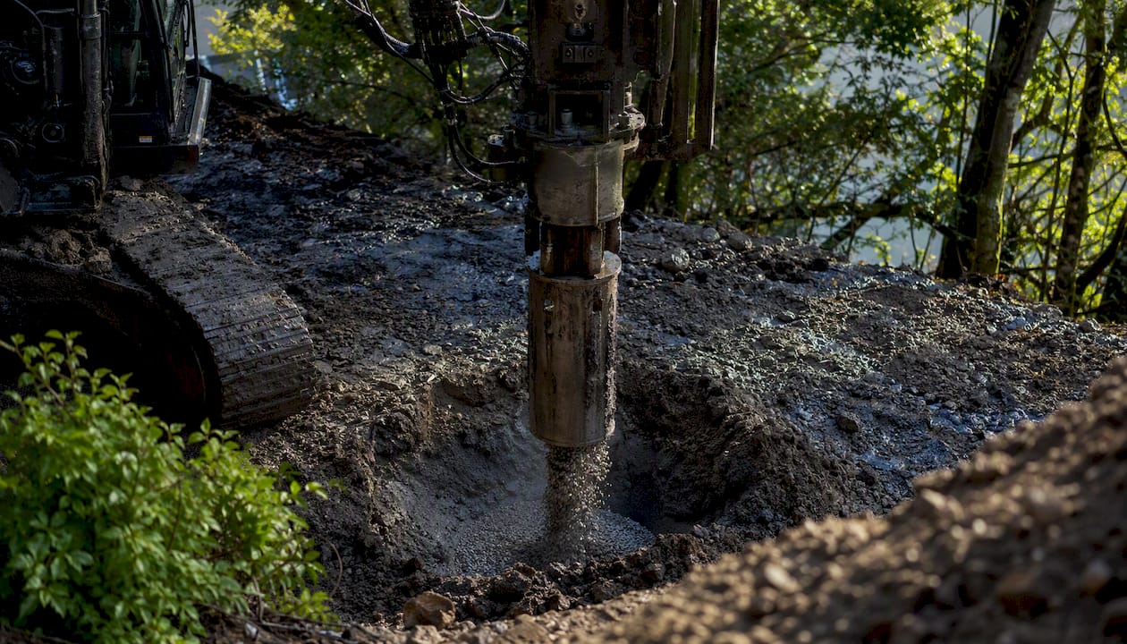
Vibro-compaction, by contrast, densifies loose granular soils (sands and gravels) by lateral displacement and vibration without backfill. It is ineffective in cohesive soils because the fines prevent particle rearrangement.
Preloading and wick drains
Preloading accelerates the natural consolidation of soft compressible clays by applying a surcharge — typically an earth embankment — before the permanent structure is built. Settlement that would otherwise occur over decades under the permanent load is induced during the preload period, leaving a stiffer, stronger subgrade for construction. Wick drains (prefabricated vertical drains, PVDs) reduce drainage path lengths from metres to centimetres, cutting consolidation time from years to months.
Soil nailing and reinforced soil
Soil nailing installs closely spaced steel bars into an existing slope or excavation face, creating a composite reinforced mass. It suits stiff to firm cohesive soils and weak rocks where the nail can be installed without the borehole collapsing. Temporary or permanent facing — shotcrete, precast panels or geosynthetic wrap — prevents surface erosion and local failure between nails. Reinforced soil walls use geosynthetic or metallic reinforcement layers within a compacted fill to create a self-supporting structure, replacing conventional concrete retaining walls in many road and embankment applications.
Pro Tip: Before mobilising plant for any mechanical treatment, confirm the as-built moisture content of the subgrade against the laboratory optimum. Compacting wet of optimum on a cohesive subgrade can lock in pore pressures that reduce long-term strength, even when density targets are met on the day. The laboratory and site team must agree on moisture acceptance windows before work starts.
Chemical stabilisation methods explained
How binders change soil behaviour
Chemical stabilisation works through three principal mechanisms. Cementation (cement) produces calcium silicate hydrate (CSH) and calcium aluminate hydrate (CAH) gels that bind soil particles into a rigid matrix, increasing UCS and reducing permeability. Cation exchange and pozzolanic reaction (lime) first reduces PI through calcium ion exchange with clay minerals, then produces long-term pozzolanic strength as calcium reacts with silica and alumina from the clay. Polymer and enzyme binding coats particles or fills pore spaces, reducing permeability and improving workability without the alkalinity of cement or lime.
The geotechnical review confirms that mismatching binder and soil mineralogy is a primary cause of stabilisation failure: applying cement to a high-PI clay without lime pre-treatment can produce inadequate strength gain, while lime applied to a sulphate-bearing soil can trigger ettringite formation and heave.
Binder-by-binder guidance
Cement suits soils with PI ≤ 20. Tests include UCS at 7 and 28 days, CBR after soaking, and resilient modulus for pavement applications.
Lime (quicklime or hydrated lime) suits high-PI clays (PI > 20). The Eades and Grim test determines the minimum lime content needed to raise pH to 12.4, the threshold for pozzolanic reaction. Lime treatment is a two-stage process: an initial mellowing period (24–48 hours) reduces PI and improves workability before final mixing and compaction. INDOT design procedures formalise this: quicklime or hydrated lime is recommended where PI > 20, cement where PI ≤ 20.
Fly ash and GGBS are industrial by-products with pozzolanic or latent hydraulic properties. A 2026 MDPI review found that industrial by-products can match or exceed conventional binders in UCS and CBR tests, but warned that compositional variability and durability concerns require rigorous site-specific testing and standardised design protocols. GGBS-steel slag combinations produced substantially higher 28-day UCS in some studies. Activation strategy — the ratio of GGBS to activator (lime, cement or alkali) — must be confirmed by laboratory testing for each source material, as composition varies between suppliers and batches.
Bitumen emulsion stabilises granular soils and weak rocks for road base applications, waterproofing the treated layer and providing flexible binding. It is less suited to cohesive soils because the emulsion cannot coat clay particles effectively.
Polymers and enzymatic binders are proprietary products with variable performance data. They can reduce permeability and improve workability but lack the standardised design framework of cement and lime. Independent laboratory testing against project-specific soils is mandatory before specification.
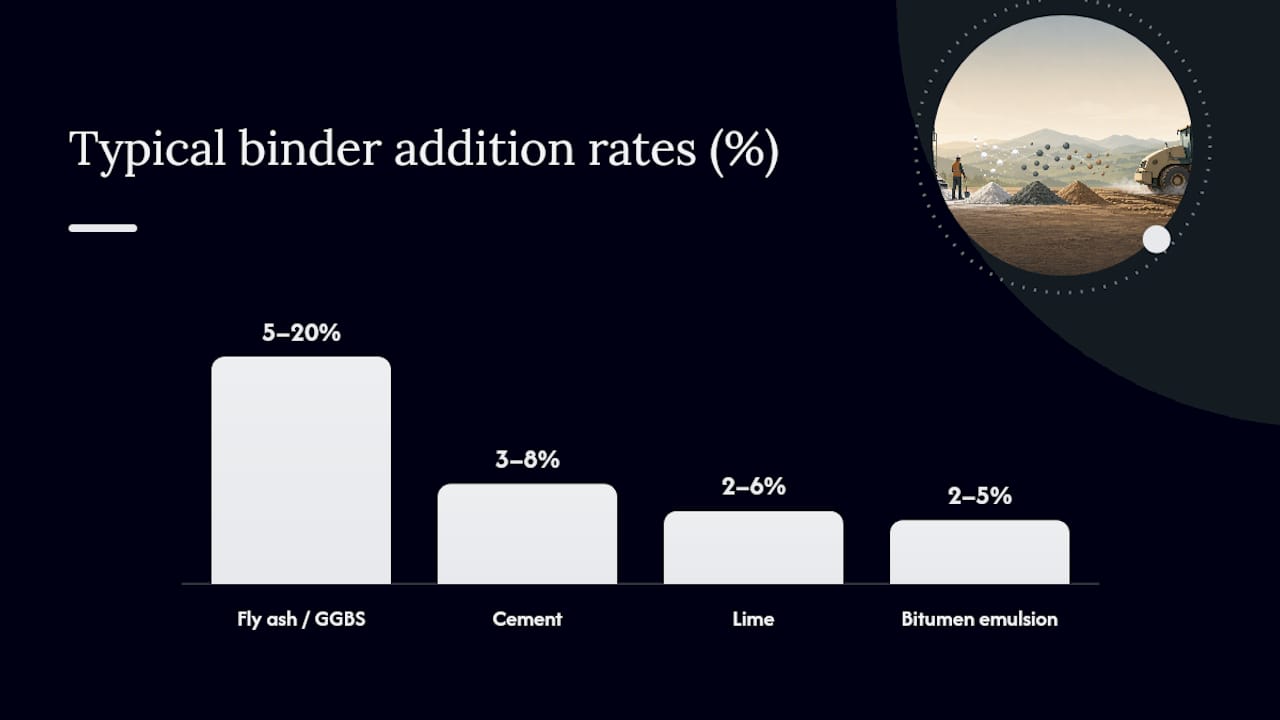
| Binder | Typical addition rate (% dry weight) | Best-suited soil | Key laboratory tests | Primary durability risk |
|---|---|---|---|---|
| Cement | 3–8% | PI ≤ 20, granular to low-plasticity | UCS 7/28 day, CBR soaked, sulphate check | Sulphate attack, frost |
| Lime | 2–6% | PI > 20, cohesive clays | Eades & Grim, UCS 28 day, swell test | Sulphate heave, carbonation |
| Fly ash / GGBS | 5–20% (with activator) | Variable; confirm by test | UCS 28 day, CBR, resilient modulus | Compositional variability, leaching |
| Bitumen emulsion | 2–5% | Granular, low fines | Marshall stability, ITS | Stripping, ageing |
| Polymer / enzyme | Supplier-specific | Variable | UCS, CBR, permeability | Limited long-term data |
Sustainability trade-offs
Cement and lime carry significant embodied carbon: Portland cement production emits approximately 0.8–0.9 tonnes of CO₂ per tonne of product. Industrial by-products such as GGBS and fly ash offer lower embodied carbon, but their variability means QA costs rise. The sustainability case for by-products is strong in principle; the practical constraint is the absence of standardised design protocols for many combinations, which pushes designers back to conventional binders for risk management.
Grouting, jet grouting and deep soil mixing
Permeation and compaction grouting
Permeation grouting injects a low-viscosity grout (cement-bentonite, microfine cement or chemical grout) into the pore spaces of a granular soil without displacing the soil structure. It suits medium to coarse sands and gravels where permeability allows grout penetration; it is ineffective in fine-grained soils. Applications include underpinning, cut-off walls and void filling beneath existing structures.
Compaction grouting injects a stiff, low-mobility grout that displaces and densifies the surrounding soil rather than permeating it. It is used to treat loose fills, collapsible soils and sinkholes, and for controlled lifting of settled structures.
Jet grouting
Jet grouting uses high-pressure fluid jets to erode and mix soil with a cement grout in situ, forming columns or panels of soilcrete. It can treat almost any soil type, including cohesive clays where permeation grouting fails. Typical column diameters are 600–2,000 mm depending on jet energy and soil type. Applications include underpinning, excavation support, cut-off walls and ground improvement beneath existing foundations.
A typical jet grouting operation proceeds as follows:
- Drill to the target depth using a rotary or percussive rig.
- Withdraw the drill string while simultaneously injecting cement grout at high pressure (typically 200–400 bar) through nozzles in the monitor.
- Rotate and withdraw at a controlled rate to produce a column of uniform diameter.
- Allow columns to cure for a minimum of 28 days before loading.
- Core and test representative columns to confirm UCS and diameter.
Deep soil mixing
Deep soil mixing (DSM) uses auger-mounted mixing paddles to blend binder (cement, lime or GGBS slurry) with soil in situ, forming discrete columns or a continuous treated mass. Mixing rigs can reach depths of 20–30 m. DSM is particularly effective in soft clays and organic soils where conventional chemical treatment is impractical. Discrete columns are designed as piles or as a reinforced grid; continuous panels form cut-off walls or mass stabilisation blocks.
Quality control in DSM relies on monitoring binder injection rates, rotation speed and withdrawal rate during installation, combined with coring and UCS testing of hardened columns.
| Method | Typical treated depth | Indicative cured UCS range | Suited soil types |
|---|---|---|---|
| Permeation grouting | 2–20 m | 0.5–5 MPa (cement grout) | Coarse sands, gravels |
| Compaction grouting | 2–15 m | Soil densification, no UCS target | Loose fills, collapsible soils |
| Jet grouting | 2–30 m | 2–15 MPa (soilcrete) | All soil types |
| Deep soil mixing | 3–30 m | 0.5–5 MPa (cement-soil mix) | Soft clays, silts, organics |
UCS ranges are indicative only; actual values depend on binder content, soil type and curing conditions. Site-specific testing is required.
Environmental interaction is a key consideration for all grouting methods. Cement grout raises pore water pH significantly; in sensitive groundwater environments, a hydrogeological assessment and monitoring plan are required before works commence.
Geosynthetics, geocells and fibre reinforcement
Product classes and principal mechanisms
Geosynthetics cover a broad family of manufactured products, each serving a distinct function:
- Geotextiles (woven and non-woven): provide separation between dissimilar layers (e.g., subgrade and granular capping), filtration, and drainage. Non-woven geotextiles also act as cushioning layers beneath geogrids.
- Geogrids (uniaxial and biaxial): provide tensile reinforcement within granular layers, increasing bearing capacity and reducing rut depth. Interlocking aggregate within the grid apertures creates a mechanically stabilised layer.
- Geocells: three-dimensional honeycomb structures filled with aggregate or soil, confining the fill and distributing load over a wider area. Particularly effective on very soft ground where conventional aggregate placement is impractical.
- Geomembranes: impermeable sheets used for containment, cut-off and waterproofing rather than reinforcement.
Installation quality governs performance. Overlaps must meet the manufacturer’s minimum (typically 300–500 mm for geotextiles, 500–750 mm for geogrids on weak subgrades). Anchoring at the edges prevents lateral pull-out during trafficking. Compaction of the first aggregate layer above a geosynthetic must use light plant to avoid puncture or displacement before adequate cover is achieved.
Pro Tip: The most common installation error is placing the first aggregate layer with a heavy tracked machine before sufficient cover exists. A minimum of 150–200 mm of compacted aggregate above the geosynthetic is needed before standard plant can operate without risk of damage. Mark this threshold on the site programme and enforce it at the pre-start briefing.
Fibre reinforcement
Random fibre reinforcement mixes short fibres (polypropylene, glass, or natural fibres such as coir or jute) into the soil before compaction, creating a three-dimensional reinforcing network that resists tensile cracking and improves post-failure ductility. A laboratory study reported that coir fibre increased the CBR of an expansive soft soil by approximately 335% at an optimum content of 0.6% short fibre by dry weight of soil; fibre content beyond the optimum reduced strength, confirming that dosage must be established by laboratory testing for each soil.
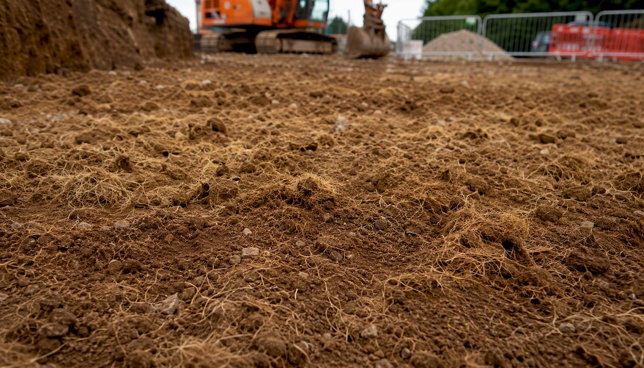
Natural fibres offer a lower-carbon alternative to synthetic options, but a state-of-the-art review noted that natural fibres have a limited effective lifetime in wet subsoil conditions due to biodegradation, and that hybrid mixes incorporating small cement additions often perform best in trials. Slope stabilisation using fibre-reinforced soil is one application where this hybrid approach is gaining traction; practical slope solutions illustrate how reinforced soil can replace structural retaining elements in appropriate conditions.
Design and laboratory testing essentials
Site investigation requirements
A stabilisation scheme is only as reliable as the site investigation underpinning it. Minimum requirements for a stabilisation project include:
- Trial pits and boreholes at sufficient density to characterise the subgrade variability (typically one per 500–1,000 m² for road schemes, closer spacing for variable ground).
- In-situ tests: dynamic cone penetrometer (DCP), plate load test or CBR in-situ to characterise the untreated subgrade.
- Groundwater monitoring: at least one full seasonal cycle where possible, or piezometers installed during investigation.
- Contamination screen: total and soluble sulphate, organic content, pH and hydrocarbon screening as a minimum; extended suite if site history suggests contamination.
- Atterberg limits, particle size distribution and specific gravity on representative samples from each identified stratum.
Laboratory mix design workflow
- Confirm soil classification (Atterberg limits, PSD, organic content, sulphate content).
- Select candidate binder type based on PI and mineralogy.
- Prepare trial mixes at three to five binder contents bracketing the expected optimum.
- Compact specimens to the project compaction standard (modified Proctor or vibrating hammer per BS EN 13286-2).
- Cure specimens at 40°C (accelerated) or 20°C (standard) for 7 and 28 days.
- Test UCS, soaked CBR and (for pavement design) resilient modulus.
- Select the optimum binder content that meets the specification target with an appropriate margin.
- Confirm durability: freeze–thaw cycling, wet–dry cycling and leachate testing where required.
Specification checklist
A robust specification for stabilisation works should include:
- Binder source, grade and certification (CE marking or equivalent).
- Minimum and maximum binder addition rate by dry weight of soil.
- Mixing equipment type and minimum mixing passes.
- Compaction standard (method or end-product specification) and layer thickness.
- Minimum curing period before trafficking or loading.
- In-situ testing frequency: density and moisture at minimum one test per 500 m² per layer; field CBR or plate load at agreed intervals.
- Acceptance criteria for each test, with clear non-conformance and remedial procedures.
Construction practice and on-site quality control
A well-designed stabilisation scheme can fail on site if construction controls are inadequate. The following sequence applies to a typical in-situ chemical stabilisation programme.
- Site preparation: strip topsoil and organic material to the design formation level. Proof-roll the exposed subgrade and mark soft spots for additional treatment or undercut.
- Binder delivery and storage: check delivery documentation against the specification. Store quicklime in sealed silos; protect hydrated lime and cement from moisture. Record batch numbers and delivery dates.
- Pre-treatment moisture conditioning: if the subgrade is wet of optimum, allow drying or add quicklime for initial drying before full treatment. If dry of optimum, pre-wet to within the acceptance window.
- Binder spreading: calibrate the spreader against the target application rate before each shift. Spread binder uniformly and avoid working in high wind to limit dust.
- Mixing: use a purpose-built rotary mixer or stabilisation train to achieve full-depth mixing. Make a minimum of two passes. Check mixing depth with a probe after each pass.
- Compaction: compact immediately after mixing using a vibrating roller appropriate to the layer thickness. Achieve the specified density (typically 95–100% of modified Proctor maximum dry density).
- Curing: protect the treated layer from desiccation (polythene sheet or light water spray) and frost for the specified curing period. Avoid trafficking until the minimum curing period has elapsed.
- In-situ testing: carry out nuclear density gauge or sand replacement tests, field CBR or plate load tests, and record results against acceptance criteria before placing the next layer.
Quality control checklist
- Density and moisture: minimum one test per 500 m² per layer, with results plotted against the laboratory compaction curve.
- Field CBR or plate load: at agreed frequency (typically one per 1,000 m² or per day of production).
- Compaction records: roller passes, speed and amplitude logged continuously where possible.
- Sampling for UCS: minimum three specimens per 500 m² of treated area, cured and tested at 7 and 28 days.
- Curing log: temperature and moisture records throughout the curing period.
- Non-conformance register: document all failures, causes and remedial actions.
For grouting and DSM operations, trial panels are mandatory before production works. A trial panel tests the proposed mix design, injection parameters and equipment calibration against the specified UCS and geometry. Core the trial panel after the minimum curing period and test UCS before proceeding.
Pro Tip: Sequence your acceptance testing so that the 7-day UCS result is available before the next layer is placed. Agree this trigger level with the designer before works start.
Environmental, health and safety considerations
Dust, fumes and VOC control
Quicklime and cement generate significant dust during spreading and mixing. Dust suppression measures include:
- Restricting spreading to calm weather conditions (wind speed below 5 m/s).
- Using enclosed spreader systems where practicable.
- Providing RPE (FFP3 respirators) and eye protection for all operatives within the exclusion zone.
- Establishing a downwind exclusion zone during spreading operations.
Bitumen emulsion and polymer binders can release VOCs during application; COSHH assessments must be completed before works start, and adequate ventilation maintained in confined areas.
Environmental risks
- Leaching: cement and lime raise pore water pH to 12–13, which can affect groundwater quality. A hydrogeological risk assessment is required on sensitive sites; monitoring boreholes should be installed where groundwater is within 2 m of the treatment zone.
- Sulphate mobilisation: lime treatment of sulphate-bearing soils can mobilise sulphate ions, increasing the risk of ettringite formation in adjacent concrete. Pre-treatment sulphate testing is mandatory.
- Spoil from grouting: grout returns and arisings from DSM operations must be managed as controlled waste. Cement-contaminated spoil is classified as hazardous if pH exceeds 11.5. Refer to UK regulations on excavation spoil management for disposal obligations.
Sustainability
The embodied carbon of cement and lime is the primary sustainability concern in chemical stabilisation. Industrial by-products (GGBS, fly ash, steel slag) offer lower embodied carbon, and the MDPI 2026 review confirms they can match conventional binders in strength tests. The constraint is compositional variability: without standardised design protocols and rigorous QA, substitution carries risk. Embodied carbon reporting is increasingly required by clients and local authorities. Contractors should be able to provide Environmental Product Declarations (EPDs) for binders used.
Safety for deep mixing and grouting
- Drill rig exclusion zones: minimum 1.5 times the rig height, enforced by physical barriers.
- High-pressure injection lines: pressure-tested before use; no personnel within the exclusion zone during injection.
- Overhead services: full utility survey and CAT scan before any drilling commences.
- Confined space procedures: where grouting is carried out in basements or below-ground structures.
How to choose the right stabilisation method
The decision is driven by six criteria, assessed in order:
- Soil mineralogy and PI: the primary filter. High-PI clays point to lime or DSM; low-PI or granular soils point to cement or vibro-compaction.
- Depth of treatment required: surface treatment (0–500 mm) suits chemical methods with conventional plant; 0.5–5 m suits stone columns or DSM; greater depths require grouting or piling.
- Loading and performance target: light trafficking needs CBR ≥ 5%; heavily loaded industrial slabs may need UCS > 3 MPa. The target drives the binder content and method.
- Groundwater: high groundwater limits compaction effectiveness and affects binder curing; grouting and DSM can work below the water table; lime and cement treatment above the water table only.
- Programme: chemical treatment with conventional plant is fast (days to weeks); preloading takes months; grouting and DSM require specialist mobilisation (weeks).
- Access and vibration sensitivity: stone columns and vibro-compaction generate significant vibration; adjacent structures or services may preclude their use.
Decision matrix (common site profiles)
- Soft clay subgrade, road formation, PI 30–50, depth 0–400 mm: lime treatment at 3–5%, target CBR ≥ 15%.
- Loose sand fill, industrial floor, PI < 10, depth 0–300 mm: cement treatment at 4–7%, target UCS 1.5–2.5 MPa.
- Very soft alluvial clay, embankment, depth 3–8 m: stone columns or DSM with cement-GGBS slurry.
- Granular subbase, pavement, PI < 5: cement-treated base per TAC guidance; fly ash as partial cement replacement where QA supports it.
- Existing structure, settlement remediation: compaction grouting or jet grouting.
Questions to ask prospective contractors
Before appointing a stabilisation contractor, ask:
- Can you provide laboratory mix design reports for this specific soil, not a generic data sheet?
- What is your equipment calibration record for binder spreaders and mixing rigs?
- How do you demonstrate mixing depth and uniformity on site?
- What is your proposed testing frequency and acceptance criteria?
- Have you carried out a trial section on a comparable project, and can you share the results?
- How do you manage non-conformances and what is your remedial procedure?
A trial section is strongly recommended for any scheme covering more than 2,000 m² or using an unfamiliar binder. Success criteria should be defined in the specification before the trial: target density, UCS at 7 days, and field CBR at a defined curing age.
Expected performance and lifespan of stabilised layers
Stabilisation is not a permanent fix in all cases. Lifespan depends on the method, the environment, and the quality of construction.
- Lime or cement-treated subgrade: well-constructed and protected from moisture cycling, a treated subgrade can remain effective for the design life of the pavement (typically 20–40 years). Poorly cured or trafficked before strength gain is complete, it may degrade within a few seasons.
- Cement-treated base (CTB): designed as a structural layer, CTB typically performs for 20–30 years in road applications before fatigue cracking requires maintenance intervention.
- Stone columns: the columns themselves do not degrade, but the surrounding soil may consolidate further over time. Settlement monitoring for 12–24 months after construction is standard practice.
- Geosynthetics: synthetic geotextiles and geogrids have design lives of 50–120 years in buried conditions, confirmed by accelerated ageing tests. Natural fibre products degrade within 2–10 years in wet subsoil, as the MDPI materials review notes, making them suitable only for temporary applications or hybrid mixes.
Deterioration mechanisms
- Moisture cycling: repeated wetting and drying causes shrink-swell in treated clays, progressively breaking down the cemented matrix.
- Freeze–thaw: water in pores expands on freezing, disrupting the treated layer. Frost-susceptible soils below the frost line require protection or a frost-resistant binder.
- Sulphate attack: ettringite formation in cement or lime-treated sulphate-bearing soils causes expansion and cracking over months to years.
- Biological degradation: natural fibres and some polymer binders degrade in the presence of soil microorganisms and moisture.
Maintenance and inspection
Owners should plan for annual surface inspections of stabilised pavements and platforms, with drainage maintenance to prevent water ponding above treated layers. After extreme weather events (prolonged drought, severe frost, or flooding), a proof test (plate load or DCP) confirms that the treated layer retains its design capacity. Drainage maintenance is the single most cost-effective maintenance action: a well-drained stabilised layer lasts significantly longer than a waterlogged one.
Contractor-focused E-E-A-T: what to require and what to demonstrate
Proofs to request from a contractor
Any contractor tendering for stabilisation works should be able to provide:
- Laboratory mix design reports prepared for the specific soil from the project site, not generic product data.
- Trial section results including density records, UCS at 7 and 28 days, and field CBR.
- Equipment calibration certificates for binder spreaders, mixing rigs and compaction plant.
- A health and safety plan covering binder handling, dust control, exclusion zones and emergency procedures.
- An environmental risk assessment covering leaching, groundwater interaction and spoil disposal.
- COSHH assessments for all binders and admixtures.
Sustainability actions for contractors
- Specify industrial by-products (GGBS, fly ash) where laboratory testing confirms performance, and document the embodied carbon saving against the cement baseline.
- Maintain a material reuse plan: treated arisings from one area of a site can often be reused as capping on another, reducing import and disposal costs.
- Provide Environmental Product Declarations for binders used, and include embodied carbon data in project completion reports.
- Record and report binder consumption against the design quantity; significant over-consumption indicates mixing or calibration problems.
Pro Tip: Include a warranty clause in the stabilisation subcontract requiring the contractor to return and remediate any area that fails a proof test within 12 months of practical completion, at no additional cost. Define the proof test type, acceptance threshold and testing protocol in the contract documents — a vague warranty is unenforceable.
The civil engineering site preparation guide and the earthworks best practice guide provide further context on how stabilisation integrates with broader groundworks planning and sequencing.
The case for laboratory-first thinking in stabilisation
The most persistent problem in soil stabilisation is not a shortage of methods. There are more binders, reinforcement products and specialist techniques available today than at any point in the history of ground engineering. The real problem is that projects still reach site with binder rates chosen from a data sheet rather than a laboratory, and with no agreed acceptance criteria for the in-situ tests that will determine whether the treated layer is accepted or rejected.
The research is unambiguous on this point. Mineralogy and PI govern which binder will work; laboratory mix design establishes the rate at which it works for the specific soil on the specific project. Skipping that step does not save money. It shifts the cost downstream, into remediation, programme delays and disputes over non-conforming work.
The sustainability argument for industrial by-products is genuinely compelling. GGBS and fly ash can deliver comparable strength to cement at lower embodied carbon, and the evidence base is growing. But the same research that makes the case for by-products also flags their compositional variability as a real constraint. The answer is not to avoid them; it is to test them properly and write specifications that reflect the variability rather than assuming uniformity.
Natural fibre reinforcement sits in a similar position: promising laboratory results, real durability limitations in wet subsoil, and a clear path forward through hybrid mixes. The engineer who dismisses fibres entirely misses a useful tool; the one who specifies them without durability testing misses the point of the research.
The practical conclusion is straightforward. Commission the site investigation, run the laboratory programme, write the specification with enforceable acceptance criteria, and require a trial section before full production. That sequence is not bureaucracy. It is the difference between a stabilised layer that performs for its design life and one that fails in the first winter.
Groundworks and civil engineering support from Gcscontractors
Gcscontractors provides groundworks and civil engineering services in Cambridge and East Anglia, covering the full range of site preparation activities that stabilisation works sit within: formation preparation, capping and subbase construction, drainage installation, and foundation works. For building contractors and developers who need a subcontractor with the technical knowledge to specify, supervise and deliver stabilisation-ready formations, Gcscontractors brings the compliance focus and site management experience that complex groundworks demand.

Working within live environments and occupied sites is a core part of what Gcscontractors does, which matters when stabilisation works must proceed alongside other trades or within a tight construction programme. The team understands the quality control requirements that come with treated formations: compaction records, in-situ testing, curing logs and the documentation that clients and engineers need to sign off each layer before the next one goes down. To discuss your project’s groundworks requirements, contact Gcscontractors directly through the groundworks and foundation services page.
Sources
The following standards and guidance documents underpin design, testing and specification for soil stabilisation:
- ScienceDirect: S2214391218300904 (geotechnical review)
- Sustainable soil stabilisation utilising mineral-containing industrial by-products (MDPI, 2026)
- PMC article: natural fibre reinforcement study
- Design procedures for soil modification or stabilisation (INDOT 2026)
- TAC technical guidance (cement-treated base and stabilisation)
Recommended
- Managing Excavation Spoil on Site: UK Regulations and Best Practices 2026 – GCS Contractors Ltd
- How Ground Conditions Affect Foundation Costs in the UK: A 2026 Guide – GCS Contractors Ltd
- Ground Erosion Myths: Why Your Construction Site Needs More Than Just Grass (2026) – GCS Contractors Ltd
- Foundations best practices: the UK construction guide