Soakaway installation Cambridge: the homeowner’s guide
A soakaway is defined as an underground drainage structure that disperses surface water into the surrounding soil, reducing runoff from roofs, driveways, and paved areas. Soakaway installation Cambridge homeowners need to get right is governed by UK Building Regulations Approved Document H3, which sets out mandatory clearance distances, sizing rules, and testing requirements. Getting the design wrong does not just cause waterlogging. It can undermine foundations, breach planning conditions, and create costly remedial work. This guide covers everything you need to know, from soil testing and sizing calculations to step-by-step installation and the most common mistakes to avoid.
What site and soil conditions must be assessed before soakaway installation in Cambridge?
Soil type is the single most important factor in determining whether a soakaway will work. Cambridgeshire’s geology includes significant areas of heavy clay, and clay soils often fail the minimum infiltration threshold required for a compliant soakaway. That threshold matters because a soakaway in unsuitable ground simply fills with water and never empties.
Percolation testing: the required method
The industry standard for assessing soil suitability is the percolation test described in BRE Digest 365. The test measures how quickly water drains through the soil at the proposed installation depth. Clay soils with infiltration rates below 1×10⁻⁶ m/s are classified as unsuitable, and no soakaway should be installed in them regardless of design.
Carry out the test at the planned installation depth, not at the surface. Surface soil often drains faster than the subsoil beneath it, which gives a misleading result. Run the test in late autumn or winter when the water table is at its seasonal peak.
Key site constraints to check before you dig
Before commissioning any groundworks, confirm the following:
- Distance from buildings: UK Building Regulations Approved Document H3 requires a minimum of 5m from any habitable building.
- Distance from boundaries: The minimum clearance is 2.5m from any property boundary.
- Distance from other soakaways or septic drainfields: A minimum of 5m separation is required.
- Seasonal water table: Water tables in Cambridgeshire can fluctuate by 1–3 metres between summer and winter. The base of the soakaway must sit above the highest recorded water table level.
- Ground contamination: Soakaways must not be installed in contaminated ground, as they can spread pollutants through the soil.
Pro Tip: Commission your percolation test in november or december, not in a dry summer month. A test carried out in dry conditions will overestimate drainage performance and lead to an undersized system.
When a soakaway is not viable due to clay soil, a high water table, or insufficient space, the correct alternative is to connect surface water to an approved watercourse or a public surface water sewer, subject to consent from the relevant authority.
How to plan and design an effective soakaway system for a Cambridge home
Good design starts with an accurate calculation of the volume of water the soakaway must handle. The standard rule of thumb is that a 50m² roof area requires approximately 1 cubic metre of soakaway capacity, installed at least 1 metre below ground level. Larger roof areas or driveways require proportionally greater capacity, adjusted for local rainfall intensity data.
System components and layout
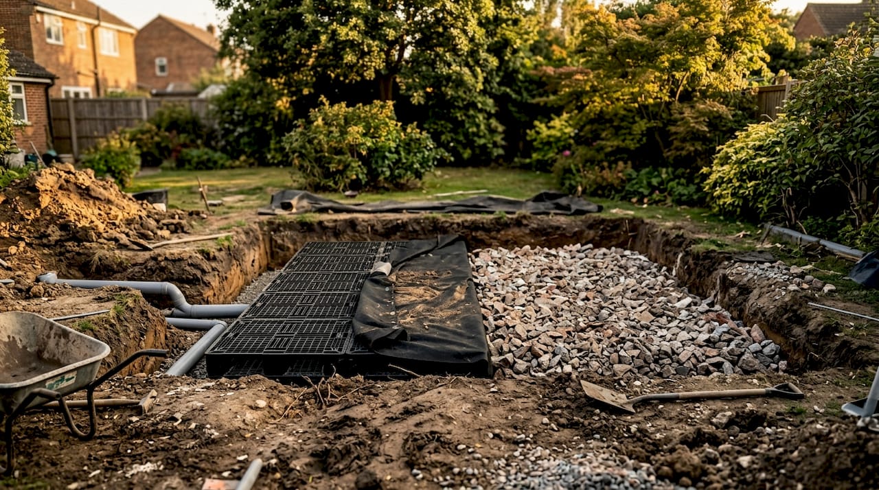
A modern soakaway uses one of two construction methods: plastic modular crates or a traditional rubble pit filled with clean angular stone. Crate systems offer a higher void ratio, meaning more storage capacity per cubic metre of excavation. Rubble pits are simpler but require a larger excavation for equivalent storage.
The table below summarises the key design parameters for a typical Cambridge residential soakaway.
| Design parameter | Requirement |
|---|---|
| Minimum distance from habitable building | 5m |
| Minimum distance from boundary | 2.5m |
| Minimum installation depth | 1m below ground level |
| Bedding layer below crate or rubble | 150mm minimum |
| Gravel cap above crate or rubble | 300mm minimum |
| Capacity for 50m² roof catchment | Approximately 1m³ |
Layout planning must also account for the inlet pipe route from the downpipe or gully, the fall required to achieve self-cleansing flow, and the position of the inspection access point. The inlet pipe should enter the soakaway at the top of the crate stack, not at the base, so that stored water does not back up into the pipe during heavy rainfall.
Integration with SuDS principles
A well-designed soakaway does not operate in isolation. Soakaway design forms part of an integrated Sustainable Drainage System (SuDS) strategy that considers the full site hydrology. For Cambridge homeowners, this means thinking about how the soakaway connects with permeable paving, rain gardens, or filter strips if the garden layout allows. Gcscontractors routinely integrates soakaway design within broader surface water drainage planning to meet both Building Regulations and local authority requirements.
Non-woven geotextile membrane must wrap the entire crate or rubble pit assembly. The membrane prevents fine soil particles from migrating into the void space over time, which is the primary cause of long-term soakaway failure.
Step-by-step guide to installing a soakaway safely and compliantly
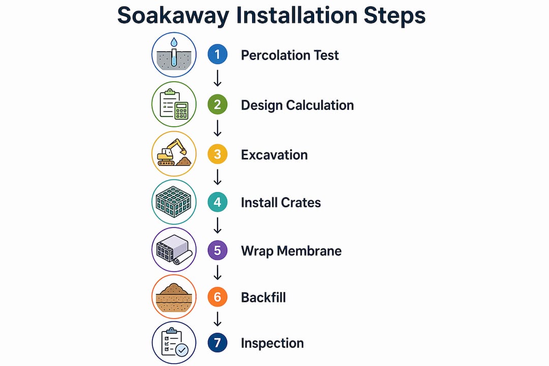
Follow these steps in sequence. Skipping or reordering them is the most common cause of installation failures that only become apparent months later.
-
Mark out and excavate. Dig to the required depth, allowing for the 150mm bedding layer beneath the crate. The base of the excavation must be hand-trimmed level. An uneven base causes crate misalignment and can crack pipe connections under load.
-
Line the excavation. Lay non-woven geotextile membrane across the base and up all four sides, leaving enough excess to fold over the top of the completed assembly. Geotextile wrapping around the crate prevents soil migration and is a Building Regulations requirement, not an optional extra.
-
Place the bedding layer. Pour 150mm of clean angular gravel (typically 20mm single-size stone) across the base and compact lightly. Do not use pea gravel or crushed limestone, as these compact too densely and restrict drainage.
-
Install the crate or rubble pit. Stack plastic crates to the required volume, or fill with clean angular stone to the required depth. Connect the inlet pipe at the top of the assembly using a watertight push-fit or solvent-weld joint. Ensure the pipe has a minimum 1:40 fall from the gully or downpipe.
-
Install inspection access. Building Control requires a rodding eye or inspection chamber upstream of the soakaway entry point. This access point allows future jetting or rodding without excavating the soakaway itself.
-
Backfill with gravel and cap. Fold the geotextile membrane over the top of the crate assembly. Place a 300mm gravel cap layer above the membrane, then backfill with selected excavated material or imported topsoil to finished ground level.
-
Reinstate the surface. For grass areas, lay turf or seed directly over the backfill. For vehicle areas, use only HGV-rated crates rated for the expected wheel loads. Standard garden-grade crates will collapse under vehicle traffic, causing ground subsidence and system failure.
Pro Tip: Photograph every stage of the installation before backfilling. Building Control may request evidence of compliance, and photographic records are far easier to produce than re-excavating a completed soakaway.
Common mistakes and troubleshooting tips for Cambridge soakaway projects
Most soakaway failures in Cambridge trace back to a small number of avoidable errors. Recognising them before installation saves significant time and money.
- Siting too close to the building. Placing a soakaway within 5m of a foundation saturates the ground adjacent to the structure. Over time, this causes differential settlement and can void buildings insurance.
- Ignoring the percolation test. Installing a soakaway in clay soil without testing is the most frequent cause of failure. The system simply fills and never drains, creating a permanent waterlogged area.
- Using undersized or garden-grade materials. Domestic plastic crates are not rated for vehicle loads. Using them beneath a driveway leads to structural collapse, often within the first winter.
- Omitting inspection access. Without a rodding eye or inspection chamber, a blocked inlet pipe requires full excavation to clear. Building Control will not sign off a soakaway without confirmed access provision.
- Skipping the geotextile membrane. Without membrane, fine soil particles migrate into the void space within a few years, reducing effective capacity and causing slow drainage.
The two clearest signs that an existing soakaway has failed are standing water on the surface above the installation and slow drainage from connected gullies after moderate rainfall. Both indicate that the void space has either silted up or that the surrounding soil can no longer accept water at the design rate.
A soakaway that drains slowly after light rain is not a minor inconvenience. It is an early warning that the system is approaching full failure. Acting at the first sign of slow drainage, by jetting the inlet pipe and checking the inspection chamber, is far cheaper than replacing the entire installation.
When a soakaway fails and the soil conditions have not changed, the most likely cause is siltation of the geotextile membrane or the void space. Jetting the inlet pipe clears blockages in the pipework. If the soakaway itself has silted, replacement is usually the only viable remedy. For Cambridge homeowners, reviewing local drainage installation guidance before any remedial work helps avoid repeating the original design errors.
Key takeaways
Compliant soakaway installation in Cambridge requires percolation testing, correct sizing to BRE Digest 365 standards, and strict adherence to the clearance distances set out in Approved Document H3.
| Point | Details |
|---|---|
| Percolation testing is mandatory | Test soil infiltration rates using BRE Digest 365 before any design work begins. |
| Clearance distances are non-negotiable | Maintain 5m from buildings, 2.5m from boundaries, and 5m from other soakaways. |
| Size to the roof catchment area | A 50m² roof requires approximately 1m³ of soakaway capacity at 1m depth minimum. |
| Geotextile membrane prevents failure | Wrap the full crate or rubble assembly to stop soil migration into the void space. |
| Inspection access is a legal requirement | Install a rodding eye or inspection chamber upstream for Building Control sign-off. |
George’s view: why most Cambridge soakaway problems are design problems
After working on groundworks and drainage projects across Cambridgeshire for many years, I have seen the same pattern repeat itself. The soakaway fails not because it was installed badly, but because it was designed without a proper site assessment. Someone skipped the percolation test, or assumed the soil was suitable because a neighbour’s soakaway worked fine 50 metres away. Soil conditions in Cambridge can change dramatically over short distances, particularly where made ground or filled areas sit alongside natural chalk or gravel deposits.
The other issue I see regularly is treating a soakaway as a standalone fix rather than part of a wider drainage strategy. Designing soakaways within SuDS frameworks is not just good practice. With the frequency of heavy rainfall events increasing across the UK, a soakaway that was adequately sized ten years ago may now be undersized for current conditions. Building in additional capacity at the design stage costs relatively little compared to the disruption of replacing a failed system.
My honest advice is this: if you are not certain about your soil conditions, commission a professional percolation test before spending anything on materials. And if the test shows your soil is unsuitable, accept that result. Forcing a soakaway into clay ground does not work, and no amount of careful installation changes the underlying hydrology. A properly designed connection to a surface water sewer or approved watercourse will serve you far better than a soakaway that fails every winter.
— George
Gcscontractors: professional soakaway and drainage services in Cambridge
Gcscontractors delivers groundworks and drainage installations across Cambridge and the wider Cambridgeshire area, with direct experience of local soil conditions, seasonal water table behaviour, and Building Regulations compliance.

Whether you need a full soakaway design and installation, a percolation test, or advice on whether your site is suitable, the team at Gcscontractors brings the technical knowledge and local expertise to get it right first time. For homeowners planning groundworks or drainage work, the groundworks contractors in Cambridge guide sets out what professional site preparation involves. To discuss your specific project, visit Gcscontractors directly and speak with a specialist.
FAQ
What is a soakaway and how does it work?
A soakaway is an underground pit filled with crates or rubble that collects surface water and allows it to drain slowly into the surrounding soil. It manages roof and driveway runoff without connecting to the public sewer.
Do I need Building Regulations approval for a soakaway in Cambridge?
Yes. Soakaway installations must comply with Approved Document H3, which sets minimum distances from buildings and boundaries and requires percolation testing to confirm soil suitability.
How much does soakaway installation cost for a Cambridge home?
Home soakaway cost varies depending on soil conditions, system size, and access. Costs are not publicly listed as a fixed rate because each site requires individual assessment. Reviewing a Cambridge soakaway cost guide for the region gives a useful starting point.
Can I install a soakaway in clay soil?
Clay soils with infiltration rates below 1×10⁻⁶ m/s are classified as unsuitable for soakaways under BRE Digest 365. In those conditions, connecting to a surface water sewer or approved watercourse is the correct alternative.
How do I know if my soakaway has failed?
Standing water above the soakaway and slow drainage from connected gullies after rainfall are the two primary signs of failure. Both indicate that the void space has silted up or that the soil can no longer accept water at the required rate.
Recommended
- Drainage installation Cambridge: the homeowner’s guide
- Cost to Install a Soakaway in Ely: 2026 Price Guide and Local Factors – GCS Contractors Ltd
- Residential Drainage Systems: A Guide for Homeowners and Developers in Cambridge – GCS Contractors Ltd
- Septic Tank Installation in Cambridge: A Guide to Local Groundworks – GCS Contractors Ltd
Need drainage work in Cambridge? GCS Contractors Ltd installs soakaways, attenuation tanks and foul & surface water drainage to Building Regulations Part H. See our drainage services in Cambridge or call 07500 570 926 for a free quote.